LWIPV6
Contents |
LwIPv6
Stack’s architecture and software layers
LwIPv6 is an IPv4/IPv6 hybrid stack and its architecture is based on the logical model called “one process for message”. In this model all the operations are performed by single thread and network protocols are rappresented by a set of API used during I/O operations.
On LwIPv6, Network Layer protocols (e.g.: IP, ICMP) and Transport Layer protocols (TCP,UDP) are handled by a single main thread which is separated by the application thread.
The stack sends and receive data throw several “virtual” network interfaces. Each network device has got its “driver” and its execution thread: the first one implements I/O functions and takes care about the “phisical” layer and the Datalink layer; the interface’s thread must use driver’s functions to read incoming data from the “virtual network”.
All stack’s threads (main thread, interfaces threads) and the application’s thread comunicate with each other by using Message-Passing APIs, Semaphores and Call-back functions. To make the interaction between the application and the Stack easier, LwIPv6 comes with two different Application Level API: the Netconn library and an implementation of the BSD Sockets Library.
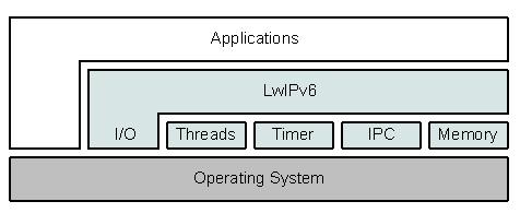
In the following picture you can see the LwIPv6’s global architecture and the several stack’s layers and exectucion threads.
The abstraction layer
In order to make LwIPv6 portable, the specific function calls and data structures provieded by the operating system are not used directly in the code. Instead, when such functions are needed the operating system emulation layer is used. The operating system emulation layer provides a uniform interface to operating system services such as timers, process synchronization, and message passing mechanisms. In principle, when porting LwIPv6 to other operating systems only an implementation of the operating system emulation layer for that particular operating system is needed.
The Operating System’s memory management is masked too by using very few API. The only operating system’s functions used directly without a wrapping API is rappresented by the I/O mechanisms.
On a unix-like operating system, this abstraction layer could be implemented by using the standard Posix API for thread and syncronization primitives and the standard C library for memory management.
I/O
LwIPv6 uses the operating system’s I/O primitives only inside virtual network device drivers. Inside the driver code the stack could launch operating systems specific functions like open(), send(), recv(), ecc...
There are few LwIPv6 features that use particular system-calls in other points of the stack’s code, like the support for the UMView select() mechanism, but these are very particular cases.
Multi-threading
The abstraction layer provides only one functions for creating new threads:
sys_thread_t sys_thread_new(void (* thread)(void *arg),
                            void *arg, int prio);
The functions sets up a new execution thread and launchs the function thread with arg as input parameter. If the function terminates successfully, it returns a new thread descriptor. This functions MUST be used only inside the stack code. LwIPv6 doesn’t provide any other functions for thread handling and nobody can stop or kill the new thread.
Semaphores
Semaphores are used inside LwIPv6 for thread syncronization. Each semaphore is identified by a sys_sem_t descriptor. To create a new semaphore call this function:
sys_sem_t sys_sem_new(u8_t count);
Only two operations are allowed on a semaphore: Signal (V) e Wait (P) and are performed by calling these API:
void sys_sem_signal(sys_sem_t sem);
void sys_sem_wait(sys_sem_t sem);
int sys_sem_wait_timeout(sys_sem_t sem, u32_t timeout);
The function sys_sem_wait_timeout() blocks the calling thread on the semaphore until a signal occurs or the timeout expires.
Message-passing
The comunication between threads is implemented by using a simple message-passing mechanism based on message queues or “mail boxes”. Mailboxes allow only two basic operations: the insertion (Post) and the removal (Fetch) of messages into and from the mailbox (Post). A new mailbox can be created with the following function:
sys_mbox_t sys_mbox_new(void);
Messages exchanged by threads are basically memory pointers. Communication is performed by using the following I/O functions:
void sys_mbox_post(sys_mbox_t mbox, void *msg);
void sys_mbox_fetch(sys_mbox_t mbox, void **msg);
If a thread attempts to read from an empty mailbox with sys_mbox_fetch(), it will block until an other thread pushes at least one new message inside the box.
Timers
A timer is a sequence of instructions (a function) executed only one time when a timeout expires. Each thread has its own timers and there is no limit to number of timers anybody can register for each thread. Well, this is not really true because there is limit to the number of timer descriptors the user can allocate in memory.
Different threads can not access to the timers of the others threads. When a thread sets up a new timer, a new timer descriptor is stored inside a list of pending timers. The elements of this list are declared as follows:
struct sys_timeout {
  struct sys_timeout *next;
  u32_t time;
  sys_timeout_handler h;
  void *arg;
};
After time milliseconds, the function h is launched with input parameter arg. All the timers of the same thread are stored respecting the expiring time.
The functions for creating or removing timers are declared as follows:
void sys_timeout(u32_t msecs,sys_timeout_handler h,
                 void *arg);

void sys_untimeout(sys_timeout_handler h, void *arg);
A new timer is identified by both the functions h and the argument arg.
If a thread calls sys_untimeout() on a timer created by an other thread, the call fails and returns immediately.
This peace of code shows how to set up an auto-respawing update timer:
#define TIMEOUT 1000

/* This is the timeout handler */
void tcp_tmr(void *arg)
{
    char *data = (char *) arg;

    ...call your update function...

    /* set up the next timer */
    sys_timeout(TIMEOUT, tcp_tmr, arg);
}

char *dummydata = ...;

int main(int argc, char* argv[])
{
    ...
    /* Set up the timer */
    sys_timeout(TIMEOUT, tcp_tmr, dummydata);
    ...
}
Problems with timers
Timers handling is not performed in a separeted thread and it's triggered only inside the Abstraction Layer's API. What does this means? This means that a pending timer will expire only if any semaphore o message-passing functions is called after the timer's setup procedure.
For example, if you set up a new timer, the stack will check for its execution only at the first sys_*() function call.
This is a very important point because this influences also the real execution time of a timer function. If you set up a 10 seconds timeout at time T1 and, for any reason, you execute a sys_*() function after 60 seconds, your timeout function handler will be called only after those 60 seconds, regardless of the original timeout.
Memory management
LwIPv6 provides a set of API for the dynamic memory management:
void *mem_malloc(mem_size_t size);
void mem_free(void *mem);
void *mem_realloc(void *mem, mem_size_t size);
void *mem_reallocm(void *mem, mem_size_t size);
Input parameters are different but the semantic and the return values are the same of malloc(), free(), realloc() functions.
LwIPv6 comes with two different implementations: a wrapper for the standard C library functions and a dynamic memory manager which uses an hidden static RAM buffer. Under unix-like systems the first one implementation is preferred. The second one should be used only on those embedded systems coming without a dynamic memory manager.
These function are thread safe under unix-like system and when the standard C library wrapper is used.
Main data structures
The two main data structures used inside LwIPv6 are: IP Addresses and Packet buffers (sent or received). It’s very importat how they are manipulated and stored in memory.
IP Addresses
LwIPv6 can handle both IPv4 and IPv6 packets, but internally, every data structure stores IP addresses in the IPv6 (128 bit) format: IPv4 addresses are converted in the IPv4-Mapped IPv6 format; IPv6 are stored unchanged.
Network netmasks are converted in the 128 bit format too, but the first 80 bit are set to 1. For example, the netmask 255.255.255.0 (0xffffff00), is converted in the following 128 bit netmask 0xfffffff.ffffffff.ffffffff.ffffFFFF.ffffff00.
LwIPv6 stored IPv4 and IPv6 addresses inside these two structures:
struct ip4_addr {
  u32_t addr;
};

struct ip_addr {
    u32_t addr[4];
};
The convertion from 128 bit back to the 32 bit rappresentation occurs only in few point for the stack’s code. For example inside the ARP protocol code and in some functions of the Socket API where IPv4 addresses are needed (e.g.: getpeename()).
Packet Buffers
IP packets are rappresented inside LwIPv6 by using special data structures called PBuf (Packet Buffer). This data type is very similar to those data structures used inside other operating systems like the Mbuf structure (BSD systems) or Skbuff structures (GNU/Linux). The PBuf structure is defined in this way:
struct pbuf {
    struct pbuf *next;
    void *payload;
    u16_t tot_len;
    u16_t len;
    u16_t flags;
    u16_t ref;
};
The field payload points to the buffer of length len where data is stored.
An IP packet can be splitted in several no-contiguous memory buffers linked together as a simple list by using the field next.
This special linked list is called “Pbuf Chain” and the total amount of used memory is saved inside the field tot_len.
If the chain contains only one element, tot_len e len store the same value. The field ref specifies the number of active references (memory pointers) pending on the the packet.
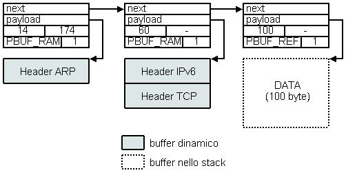
There exist four different types of Pbuf structures: PBUF_RAM, PBUF_ROM, PBUF_POOL and PBUF_REF. The first three are used to access to different types of memories (RAM, ROM or a to statically allocated buffer). The PBUF_REF type is used to mantain a reference to a memory buffer not handled by the stack's memory sub-system (e.g: the thread's stack memory).
In the following picture you can see a IP packet stored inside a “Pbuf Chain” composed by several type of Pbuf element.
To allocate a new Pbuf structure you must call the following function:
struct pbuf *pbuf_alloc(pbuf_layer layer, u16_t size,
                        pbuf_flag flag);
The parameters size and flag specify the dimension in bytes and the type of new Pbuf to create..
The layer parameter
The layer parameter specifies which kind of network headers will be encapsulated inside the new buffer. There are four level: PBUF_TRANSPORT, PBUF_IP, PBUF_LINK and PBUF_RAW. The PBUF_TRANSPORT, for example, is used to allocate enough space for the data payload plus the link layer's header (Ethernet) plus the network packet's header (Ipv4 or Ipv6) plus the transport packet's header (TCP or UDP).
This parameter is very important because everytime new data have to be sent, the stack performs the protocol encapsulation process. For each step of the encapsulation new space for an other protocol packet header have to be allocated. These buffers can be allocated by using several Pbuf packets, one for each new header, but this solution is not optimal and it can cause memory fragmentation.
With this special parameter, each new packet can be stored inside a single Pbuf element instead of using a Pbuf chain.
The following function can be used to shift the payload pointer and thereby to access to the memory locations reserved to each network header:
u8_t pbuf_header(struct pbuf *p, s16_t header_size)
In the picture you can see a PBUF_TRANSPORT Pbuf structure and the consecutive calls to pbuf_header() (from top to bottom) needed to access to the different segments of the packet.
Drivers and Network Interfaces
LwIPv6 can handle an unbouned number of network interfaces at the same time. Each network device is rappresented by a special structure called netif:
struct netif {
  struct netif *next;

  char name[2];
  u8_t num;
  u8_t id;

  unsigned char hwaddr_len;
  unsigned char hwaddr[NETIF_MAX_HWADDR_LEN];
  u16_t mtu;
  u8_t link_type;
  u16_t flags;
  void *state;

  struct ip_addr_list *addrs;

  err_t (* input)     (struct pbuf *p, struct netif *inp);
  err_t (* output)    (struct netif *netif, struct pbuf *p,
                       struct ip_addr *ipaddr);
  err_t (* linkoutput)(struct netif *netif, struct pbuf *p);
  err_t (* cleanup)   (struct netif *netif);
  void  (* change)    (struct netif *netif, u32_t type);
};
The network driver must initialize all the structure and must launch the interface’s thread. All the interfaces created by the stack are linked together in a simple list structure by using the next field.
Each interface is identified either by its logical name, composed by the fields name and num (eg. “et0”, “wl0”, “bt2”) or its id, which is an unique interger number assigned by the stack at initialization time.
The netif structure stores several informations like the network link type (link_type), the supported MTU (mtu), the physical address for the device (hwaddr) if supported and a set of flags (flag) used to save the current state of the interface (UP, DOWN, PROMISQUOSE MODE, ecc...). The field state is used by the device driver to save private data useful for the driver only.
Interface’s addresses
Each interface can use several IPv4 and IPv6 addresses, and they are stored inside the list addrs. Each entry of the list contains the IP address, the netmask and some additional flags used mainly by the IPv6 layer.
The entry structure ip_addr_list is defined as follow:
struct ip_addr_list {
	struct ip_addr_list *next;
	struct ip_addr ipaddr;
	struct ip_addr netmask;
	struct netif *netif;
	char flags;
};
The netif field keeps the reference to the interface the address belongs to.
Comunication with the stack
The network interface’s thread interacts with the stack’s thread by using the function pointers input(), output(), linkoutput(), change() stored inside the netif structure at initialization time .
For each incoming packet (eg. ARP o IP, it depends on the link type), the interface’s thread delivers it by calling the input() function. This function is usually the function tcpip_input(). When a new packet is read from the network link, the thread calls this function which simply sends the packet to the main thread by using message-passing.
N.B: The interface’s thread handles (read from the link) incoming packets only.
When the stacks need to send outgoing packets, it calls the function output(). The routine associated with the output() pointer is implemented by the interface’s driver and usually perform link-specific operations before calling the low level function linkoutput(). It’s duty of linkoutput() to "phisically" send (eg. Call write() on a pipe or a socket) the outgoing packets.
N.B: LwIPv6 comes with a set of drivers fo ARP protocol handling, but each driver has the job to use these APIs to implement the output() function.
Every time it’s necessary to change the interface state and perform special operations (e.g. flush a cache associated with the link) the change() functions is called
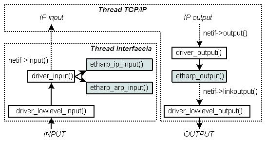
The following figure shows an example of functions called by the interface’s thread and the stack’s thread while sending and receiveing packets. In this example the interface driver handles a ethernet linnk and uses the ARP API of LwIPv6.
IP Layer
With some execptions, LwIPv6 handles IPv4 and IPv6 packets inside the same set of functions and witht the help of the same data structures. In the following sections we will show the main steps performed by the stack when a new IP packet is sent or received.
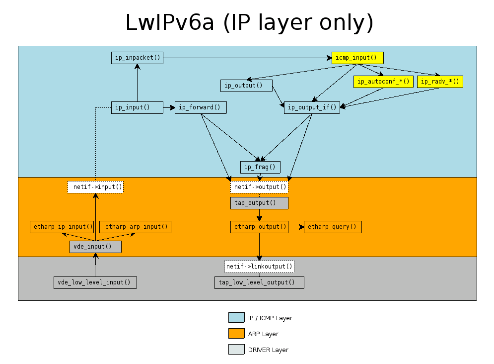
IP Input
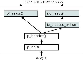
Incoming packets are read from the link by the interface’s thread and sent to the main thread throw message-passing. The main thread checks its message queue, pops the packet and calls the ip_input() function. For IPv4 packets, the function peforms the checksum validation.
The packet’s destination address is compared with all the incoming network interface. If the destination address and anyone of the interface’s addresses match, che packet is passed to the ip_inpacket() function.
This function performs IP fragmens reassemblation, if needed, and then delivers the IP packet to the transport layer of the stack.
IP Output
When anyone of the transport protocols needs to send data (TCP segments or UDP datagrams), the function ip_output() is called.
This function tries to identify the outgoing interface for the given destination and then calls ip_output_if(). If the transport layer already knows the outgoing interface, then ip_output_if() is called directly.
The ip_output_if() function performs the IP encapsulation and send the packet on ouput by calling the netif->output() function.
If the destination address belongs to anyone of the stack’s interfaces, the function pushes the packet in the stack’s message queue and the packet will be processed as a incoming packet.
When the destination IP idetifies a remote host and the packet’s length it’s larger than the link’s MTU, then IP fragmentation is performed.
IP Forwarding
IP Forwarding is an optional feature and can be eigher enabled or disabled at compilation time. This feature is useful only if the stack acts as a network router and uses several interfaces conneceted to different links.
If an incoming IP packet needs to be forwarded, the stacks checks the rouring table and then calls the ip_forward() function. This routine decrease the TimeToLive (TTL) field, or the Hop-Limit field (in IPv6), compares the packet’s length with the ourgoing link’s MTU and then calls the ip_output() function.
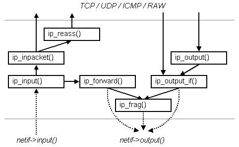
The following picture shows a simplified scheme of the IP layer’s operations sequence.
IPv6: Missing data structures
The RFC documents about IPv6 propose several data structure the correct management of input and output packets, for example the Neighbour Cache, the Prefix List), the Destination Cache and the Default Router List. All of these are used at the same time by many sub-protocols like the Neighbour Discovery, PMTU Discovery, ecc... To make the stack as simple as possible, LwIPv6 does NOT explicitly implements all these internal data structures. The many informations stored inside these caches are saved and extracted from the existing structures like the ARP table, the routing table, ecc....
IP: Reassembling and Fragmentation
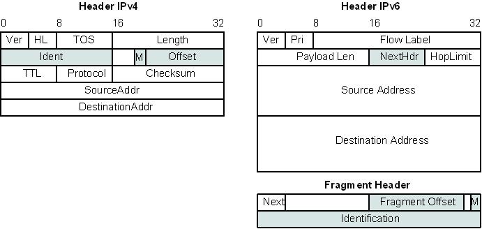
LwIPv6 supports both IPv4 and IPv6 reassembling and fragmentation of datagrams. In the picture you can see the headers and fields involved during the packet fragmentation.
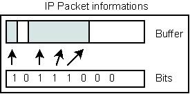
Even if IPv4 and IPv6 protocols implement this feature in very different ways, LwIPv6 uses the same data structure for supporting both protocols: a memory buffer and a bit mask used to remember the holes in the IP datagram.
The maximum number of fragmented datagrams the stack can reassmebly at the same time is defined by the costant IP_REASS_POOL_SIZE.
If a packet is not reassembled before IP4_REASS_MAX_AGE or IP6_REASS_MAX_AGE seconds, then the stack discards every information about that datagram .
For each incoming IPv6 packet, the stack calls the ip_process_exthdr() which processes IPv6 optional headers, looking for the Fragmentation Header.
Reassembling is implemented by two different functions:
struct pbuf *ip4_reass(struct pbuf *p);

struct pbuf *ip6_reass(struct pbuf *p,
                       struct ip6_fraghdr *fragext,
                       struct ip_exthdr *lastext);
These functions return NULL if no received datagram can be fully reassembled.
ICMP
LwIPv6 manages the ICMP layer as well as it manages the IP layer protocols, both ICMPv4 and ICMPv6 are handled by the same stack code.
Incoming ICMP packets, no matter what their version is, are passed to the icmp_input() function. This function perform ICMP fields validation and, if it’s necessary, sends a ICMP response on output.
Up to know, LwIPv6 supports only ECHO and ECHO REPLY messages for both ICMPv4 and ICMPv6. The stack provides a simple working implementation of the ICMPv6 layer: Neighbor Discovery, Router Discovery and Address Autoconfiguration protocols. Their implementation is not complete yet.
Transport Layer
Every connection of the Transport Layer (TCP, UDP) is identified by a connection “descriptor” which is special data structure called PCB (Protocol Control Block). A PCB saves all the informations about a connection and it is used to handle the protocol session in the proper way.
Each Transport Protocol uses a different and very specific PCB structure, but there are few informations that are common to all PCBs. These informations are: the source and destination IP addresses of the connections, a TOS (Type Of Services) parameter, the TTL (Time to Live) of the outgoing IP packets for that protocol and few additional flags (socket options) used by the Application Level APIs.
All these informations will henceforth be referred to as IP_PCB informations.
Protocol Callback functions
Every PCB stores also an other type of information, which is vital for the correct management of a transport connection: a reference (a pointer) to the protocol callback functions. These functions are called by the stack code everytime the connection state changes: the incoming of new data, the establishment of a new connection with a remote host, ecc...
The number and the type of the functions depends to the transport protocol; these differences between every PCB will be analized in the following paragraphs.
UDP
The UDP PCB structure is defined as follow:
struct udp_pcb {

  IP_PCB;

  struct udp_pcb *next;

  u8_t flags;
  u16_t local_port, remote_port;
  u16_t chksum_len;

  void (* recv)(void *arg,
                struct udp_pcb *pcb, struct pbuf *p,
                struct ip_addr *addr, u16_t port);
  void *recv_arg;
}
In the structure declaration the reader will find the common connection data (IP_PCB) and the other fields needed by the UDP layer, in particular the source and destination ports.
The function pointer recv<code> and the <code>recv_arg field are necessary for the incoming traffic management.. The recv function is the callback used by the application to process all the new incoming UDP datagrams.
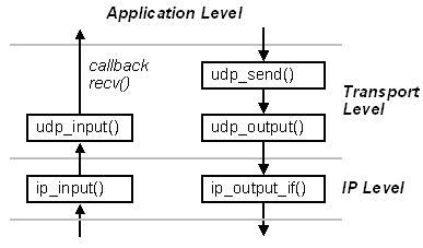
The IP Layer passes all the UDP datagrams to the udp_input() function and this one scans all the PCBs looking for the right connection and then calls the callback recv.
When the application need to send new data on output, it calls the udp_send() routine which creates the UDP packet and starts the protocol encapsulation mechanism.
In the following picture is showed the global structure of the UDP layer, with both receiving and sending actions.
The application must allocate and initialize a new connection descriptor for each UDP connection. All these operation can be performed by the application itself, but LwIPv6 comes with a implementation of the Socket library which does the hard job and hides a the details.
TCP
The TCP layer looks almost like the UDP layer, but its implementation is more complex, of course. The PCB descriptor for a TCP connection is defined as follow:
struct tcp_pcb {

  IP_PCB;

  struct tcp_pcb *next;
  enum tcp_state state;
  u8_t prio;
  void *callback_arg;

  u16_t local_port;
  u16_t remote_port;
  u8_t flags;

  u32_t rcv_nxt;
  u16_t rcv_wnd;
  u32_t tmr;
  u8_t polltmr, pollinterval;
  u16_t rtime, mss;
  u32_t rttest, rtseq;
  s16_t sa, sv;
  u16_t rto;
  u8_t nrtx;
  u32_t lastack;
  u8_t dupacks;
  u16_t cwnd, ssthresh;
  u32_t snd_nxt, snd_max, snd_wnd, snd_wl1, snd_wl2,
        snd_lbb;
  u16_t acked;
  u16_t snd_buf;
  u8_t snd_queuelen;
  struct tcp_seg *unsent, *unacked, *ooseq;
  u32_t keepalive;
  u8_t keep_cnt;

  err_t (* sent)     (void *arg, struct tcp_pcb *pcb,
                      u16_t space);
  err_t (* recv)     (void *arg, struct tcp_pcb *pcb,
                      struct pbuf *p, err_t err);
  err_t (* connected)(void *arg, struct tcp_pcb *pcb,
                      err_t err);
  err_t (* accept)   (void *arg,
                      struct tcp_pcb *newpcb,
                      err_t err);
  err_t (* poll)     (void *arg, struct tcp_pcb *pcb);
  void  (* errf)     (void *arg, err_t err);
};
As the reader can read in the previews structure, several informations are needed by the TCP state machine code. All the fields are used to implement the Congestion Control, the Fast Recovery/Fast Retrasmit mechanism and the Round-Trip Time Estimation.
RAW Connections/Protocols
LwIPv6 can handle RAW connections. This means that the Application Level can send hand-crafted IP datagrams and must read and process all incoming packets. The stacks manages these special connections as like as any other TCP or UDP connection. The PCB used for RAW connections is defined as:
struct raw_pcb {

  IP_PCB;

  struct raw_pcb *next;
  u16_t in_protocol;

  void (* recv)(void *arg, struct raw_pcb *pcb,
                struct pbuf *p,
                struct ip_addr *addr, u16_t protocol);
  void *recv_arg;
};
It looks like the UDP descriptor: there is a callback function (recv()), but the structure keeps informations only about the Transport protocol (in_protocol) the application want to manage.
When a new IP datagram is received, the stacks calls the raw_input() function before passing the packet to the transport layer. This functions checks if anyone of the active RAW connections matches with the new packet and then calls the callback functions.
On output, the application level sends raw data with the raw_sendto() and then the IP layer encapsulates the application datagram with the ip_output_if().
Other Images
This is an other rapresentation of the function calling sequence inside the stack. The picture shows a stack with two virtual interfaces: a VDE interface and a TUNTAP interface.
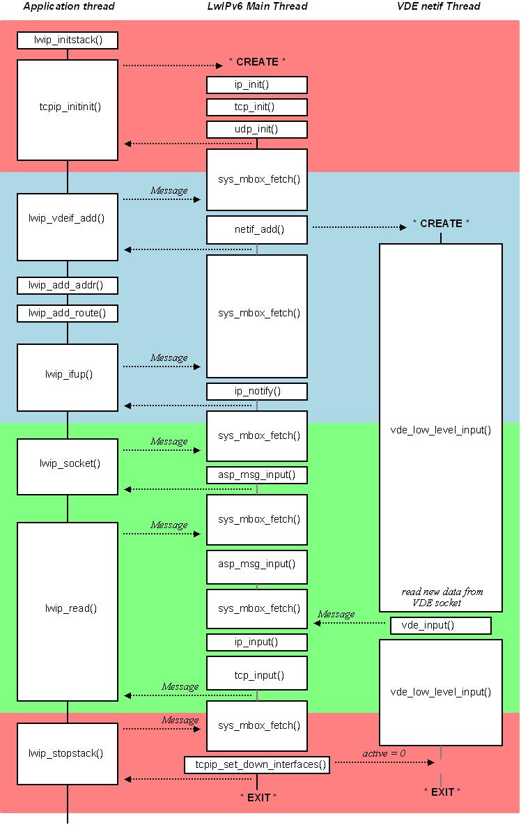
This is a very streamlined view of an application running LwIPv6.

